3D Printer Diagnostics

Good Morning from my Robotics Lab! This is Shadow_8472, and today, I am going seemingly nowhere with my printer. Let’s get started.

I got some cleaning filament today. It looks just like the “sample” that came with the printer. It doesn’t have a spool. It is a translucent white when solid. However, it’s much longer and came with two twist ties to hold it together. It actually extrudes clear and goes milky when it cools.

I spent a while messing with the cleaning filament. I shoved a bunch through the extruder tip and it still ooze a little, then curl around to touch another spot on the extruder tip and form a loop instead of a thread. I developed a hypothesis that the natural curl of the filament was influencing the curl of the extruded material, so I tested it by flipping the roll on the holder. The curl eventually went the other way, supporting my hypothesis. The printer does not appear to be clogged.

I still have a bit of gunk I want to get out so it doesn’t show up in random spots on my important, white print. I found a guide [LINK], but I seemed to regress in my abilities as I went along. The first try was okay, the second one seemed a bit broken, and the rest didn’t even come close. At one point, I even had the filament coming out a completely wrong part of the print head. I ended up turning the printer off until I can research it a bit more, but the guide I linked did say something about maintaining pressure for a couple minutes. I did manage to get a bunch of stuff out, but I have my doubts as to if I even got close to all of it.

Final Question: The curl seems to be a works as intended, but my main problem still exists. Any ideas why my filament is trickling a little when it’s otherwise warm but not extruding?

Planning a Semi-Sealed Night Light Part 5

Good Morning from my Robotics Lab! This is Shadow_8472, and today, I am going over no tangible progress. I ran out of time debating the future of another project with someone, and not even that is resolved. Let’s get started!

I haven’t been able to print anything all week. Whenever I do, the extruder tip is a little runny when it should be stopped. It ends up curling around, then sticking to the side of the tip. I cleaned it off multiple times before I realized what was going on, and I haven’t been able to figure out the correct keywords to search for the problem. I think the problem may be because the printing temperature is too hot for this particular spool of filament. The tip may also have a little clog frustrating things.

I also figured out what was with some miscolored specks in different prints I’ve done recently. The first time I spotted them, I thought they were just dust that had gotten into the print job that really didn’t want to come out. Now, I know it’s residue from previous spools. While this may just look ugly when using a single kind of plastic, if I start switching between PLA and ABS regularly, I will want a cleaning filament. I’ll want it sooner if my problem above involves a plugged tip.

In other news, my friend, who I still want to print this night-light up for, has had a situation change on her. I just found a lamp base I could use, but I may need to make the whole thing battery operated instead.

Final Question: What could cause the printer tip to leak, almost as if slowly extruding normally?

Planning a Semi-Sealed Night Light Part 1

Good Morning from my Robotics Lab! This is Shadow_8472, and today, I’m starting a new project where I install some electronics while a project is still printing. Let’s get started!

This will be a much larger print than I’ve ever done before. I know that already. I’ll be laying out the pieces of the project and ordering them as I write, just to play with the writing style.

Different parts include: Blender modeling, Laptop repair, White filament, and Assembling a circuit. If I think of more, I’ll insert them where appropriate.

Project Concept: the final product will be a gift for a friend I’ve known for a long time. It will be roughly cube shaped light printed from white PLA with relief pictures of either Angels or Cats on the sides. For extra style and practicality, I want the top sculpted to look sort of like a curved roof. A long lasting light bulb will illuminate the whole thing from the inside from atop a custom circuit board, but anything inside won’t be accessible after the print is finished.

Laptop Repair: the other week, my laptop refused to accept my power chord. It looked like a bent power pin, but it was a large piece of plastic from the port missing. That will easily take up a post when the part comes in and I cover its repair.

White Filament: I have two colors of plastic right now, black and red, neither of which would look good for a light. The plastic needs to let light through, but also go with pretty much anything.

Assembling a Circuit: this is a topic that could easily take two or three weeks and will challenge and grow my abilities the most. Simply put, I have no idea what I’m doing here, except that I need it to move power from the power chord to the light bulb, and maybe some colored LED’s around the outside. I’ll want to thoroughly test it before final installation.

Blender Modeling: this one will happen in tandem with the previous one. I’ll need to establish a maximum size for the circuit board based on how big I can make the case with the printer. But I’ll need the final measurements of the final board before I start the final print. Unless I want to toy around with an induction based power chord, I’ll need a place to plug in a power chord. It might also help if I was able to screw down the board itself.

So far, I have a fairly good idea for the overall shape modeled in Blender; I don’t think I have a good mesh yet, the boolean operator didn’t exactly like two half-cylinders intersecting like I had them doing.

Final Question: How have you aimed for something out of reach, but not so far as to (hopefully) be unobtainable?

An Experiment Rerun

Good Morning from my Robotics Lab! This is Shadow_8472, and today, I am rerunning the experiment from a few months ago to see if my Raspberry Pi is likely to melt through its PLA casing. Let’s get started!

Last time, my apparatus failed miserably. The painter’s tape holding the thermal probe in place slipped just enough to let the probe get away from the point it was supposed to be measuring. This time, I used Scotch tape, and it held. Another improvement was a custom program that ran all the CPU’s cores at 100%, compliments of the workshop I’ve been going to. I recorded temperatures to the nearest tenth of a degree instead of rounding to the nearest whole.

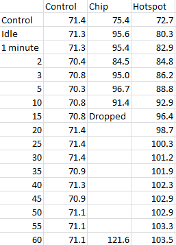
Results for today’s experiment. All measurements are in Fahrenheit.

I ran the experiment for an hour, taking measurements on a white envelope on my desk, a chip on the upward facing bottom of the Pi, and the probe measuring the target spot on the case. Measurements were taken while it was off, after the Pi had been running long enough to level off the critical spot’s temperature, and every five minutes after the test started, with extra data points at 1, 2, and 3 minutes.

I changed procedure at the 15 minute measurement, as the temperature from the chip was highly unstable, likely due to temporarily improved ventilation by removing the case’s head. After dropping this measurement, I noticed the probe temperature climb from slightly faster before stabilizing to within a degree of 102 F for the second half hour of the test, well below the glassing temperature of PLA.

Conclusion: While this case should be fine with whatever load I put on it, PLA is not the material to be making computer cases out of.

Final Question: Have you ever changed an experiment mid-procedure because you suspected your measurements were affecting your results?

A New Tool Part 13

Good Morning from my Robotics Lab! This is Shadow_8472, and today, I’ve finally completed the construction of my New Tool!

I believe it’s only appropriate that I write this post on the computer in question, a little Pac-Man themed Raspberry Pi system I’ve named Blinky Pie.

The work this week was actually fairly simple. I stopped by a local hardware store with the Pi and the case to pick up two screws, and the guy who helped me was very knowledgeable. He helped me choose screws that were big enough to hold the board, but not so big as to crack the printed plastic.

Before I did my final assembly, I did a dry run where I taped the camera in place across the top of the dome and down the other side, and it worked pretty well, so well, I only had to add a final piece to keep the camera secured.

I took the camera out to finally install the two heat sinks that came with my Raspberry Pi starter kit, a task my father was happy to help with. After that, I installed its ribbon cable around the back of the board where I could install it with the screws I picked up earlier after making sure the camera was installed correctly. Of note, I have been having a lower rate of failure when installing that thing lately.

While celebrating the final completion of the base hardware for my tool, I ended up exploring some settings on the GUI, specifically the task bar, or as Windows would call it, the Start bar. I found a setting to customise the color, and about a setting for about everything you could think of and double it. The term is called “decision fatigue.” There are so many settings, you can spend, and have to spend an hour or two to get everything looking OCD compliant. One glitch preventing using the “icons only” setting from save space has a workaround of moving the task bar to a side and back again, but that throws a bunch of other settings into chaos, mainly the height of the task bar, and guess who doesn’t have a “restore to defaults” button!

I’ve run multiple tests with the Pi idling in the case before its final installation. I’m pretty confident the case won’t melt. It’s well ventilated by the heat-sinkable chips. I even ran the dry assembly for a few hours, and the plastic around the stock board with out heat sinks was only warm.

Final Question: Besides feline repellent, what other applications can you think of for a Raspberry Pi with a camera?

A New Tool Part 10

Good Morning from my Robotics Lab! This is Shadow_8472, and today, I am covering the finishing touches of the physical side of my new prototyping assistant. Let’s get Started!

I left off with the glue mask drying on the ghost’s foot area. When I peeled off the tape from around the stuff I actually wanted to paint, I ended up pulling bits of the glue mask off along with it. I ended up spending the week touching up the glue and waiting to paint the foot.

The lower half of the Pi case finally did get painted, but at present, I am waiting to put a clear coat on the whole thing. Order of operation keeps getting in my way, though, as the upper half of the case needs some touch up paint from where I goofed on the original masking.

In other news, I went to that workshop again. I hooked up the camera to the Pi and had it look through the pinhole. I was expecting a blue haze around the picture’s outer rim, but somewhere in the process of painting, likely when I was first painting the blue pupil and I stuck a pin in it, I must have expanded the hole just enough so it doesn’t show.

To finish this week’s project (late) I just need the touchup finished with a paint brush, a light sanding to remove the strokes, and a clear coat to protect the paint. After that, the foot’s masking can come off and I can mount the Pi board and tape the camera in place. As the file I printed up is meant for a slightly different board, I will only be able to use two of the four screw holes that align at once. I’m slightly worried about too much torque on the Pi’s circuit board, but if I’m always careful, it shouldn’t be a problem.

Final Question: I’m slightly worried I won’t have enough to write about when I get around to programming the thing. Will you be up to more technobabble style posts when they come?

A New Tool Part 9

Good Morning from my Robotics Lab! This is Shadow_8472, and today, I am bringing another slow progress report. Let’s get started!

In retrospect, I spent a little more time on my project than I would likely have given myself credit for. Nevertheless, I didn’t make my goal of fully painting the case. I had to plan every step before hand, and carry them through.

Early on in the week, I once again sacrificed the texture of my fingertips as I sanded the Pi case. When I sanded the pyramid, aside from only doing half of it, I had the sandpaper flat. Flat sandpaper doesn’t work so well with curved surfaces unless you have some sort of machine to sand evenly. I’m working by hand, without any power equipment. I used different grits, mainly skipping some of the lower ones and working with something a little more appropriate to the quality it’s already on.

The 660 piece I used up was the only one in stock, so I ended up getting and using 1000 grit for polishing it. I will say, though, it wasn’t the surface without blemish I was expecting. I kept getting these rings as if the vertical layers were slightly scaled wrong.

My technique while sanding evolved as I worked. At first, I was just trying to conform the paper to the surface to sand. After a while of mildly frustratingly flimsy sandpaper slowing me down, I folded it over and focused on smaller spots at a time. Later still, my father got in there and gave me a wash cloth to use as a flexible sander block.

After sanding came masking. Now, I have two pieces. The head, and the body. The head is basically a dome with eyes, one of which I hollowed out for the camera. The body houses the Pi and has screw holes on mini shelves and ventilation holes stuffed into a waffle cone “foot” section. After an overnight test on the test pyramid, I painted the eyes first. I got out the blue painters’ tape and covered the whole outside of the head. Then I took a razor blade and cut out the pupils, scratching the lens pupil in the process. Oh well. After spraying that blue, I found a tip online to use some Elmer’s school glue as a mask. I covered the pupils in glue and uncovered the rest of the eyes before the glue finished drying. When I peeled back the glue, I realized this project might not look absolutely perfect, but it’s going to be far from ugly. I missed a few tiny spots with the glue, and still have to do a little cleanup. As it stands now, I have two coats of red paint on the main dome.

The foot is another interesting story. I decided early on I wanted to leave the inside of the case alone. I also added the uneven underside to the immunity. Since glue gets into annoying, little places, I went with that to mask off the inside of the case and the bottom of the foot. However, the inside of the case has some spots I doubt I will ever be able to clean, such as screw holes. So I covered the little holes on the inside, masked off the parts I wanted covered, and applied glue as the positive mask; this is where it stands now, waiting for the globs of glue I used to finish drying. Once that’s done, I will remove the negative mask and paint the lower half. With any luck, I will just have to get the glue out and install the hardware and I will have a tiny prototyping assistant for many projects to come.

Final Question: With any luck, I will be working on the software side by the end of next week, but I still don’t have a way to physically make the high frequency to repulse naughty cats. What would be a good place to look?


A New Tool Part 8

Good Morning from my Robotics Lab! This is Shadow_8472, and today, I am taking a little side quest to try out some techniques so I can paint my Raspberry Pi case and have it look good. Let’s get Started.

I decided to paint one or more of my old test prints. The first two were an acrylic paint straight onto the plastic. It didn’t work all that well. I couldn’t even get a small piece devoid of any brush strokes, and I want a smooth finish. On top of that, I was able to easily scrape off part of the paint with my finger nail after it was fully dry.

My next step took the rest of the time for the week. I moved over to a goal of spray painting, so I printed up another pyramid from when I tried to figure out if the percent completed was in terms of time, z axis, or plastic used.

I was thinking of testing both sanded and unsanded surfaces, so I was going to print it twice, but I cut back and only sanded half of it. I still have the original around, but I wanted to leave that one alone as sort of a memory piece. Printing it again reminded me of how difficult the raft was to get off.

After getting most of the raft off, I got out the sandpaper, going through grits of 80, 150, 220, 320, and 600, using water for the fine grits on “waterproof” paper, and I actually got it pretty smooth. I did get the stubborn part of the raft off. After going back and forth on what part of the model to mask off first, I decided on using some blue painters’ tape to mask off the very top and dangling the whole thing off that. I applied two layers of white spray paint, including the bottom (primer included in paint). I let it sit for a day over Sabbath. After it had the recommended 24 hours to dry, I masked off the rest of the pyramid body and painted the capstone yellow.

As I peeled back the masking, I saw a few spots where I didn’t make sure the tape was perfectly creased in there and it leaked in. Lesson learned: use your thumbnail ensure the quality of your masking.

In the end, I like the smoother sides. The little ridges from printing poke out a little, and I’m not sure if they are catching dirt or wearing through, but I think it may be worth it to put the bit of extra effort to make the final product just that much better.

Final Question: I’ve been thinking of including a sub-title for multi-part projects. This one would have been something like: “(Side Quest: Painting Skills)”, but that makes it harder to just edit the URL to jump to adjacent posts. I know I don’t likely have enough regular readers to warrant this question, but should I include subtitles?

A New Tool Part 7


Good Morning from my Robotics Lab! This is Shadow_8472, and today, I have a short post because the printer did most of the work. Let’s get started.

The printer took a little over two days to print. It went all right, except one time when the PVC pipe extending the filament holder slowly slipped out. It made a loud sound and I was able to repair the accident before anything print-ending happened.

Cleanup was actually not as bad as I was expecting. As with the practice ring, the slot to accommodate the HDMI, power, and sound needed attention. But the custom eye slot was one of the cleanest to come out of the printer yet. It only had the single most tricky tag to remove of all. After I poked it with a razer blade for a while, my father used a candle to heat a blade to melt it off. I’m a little annoyed some soot ended up sticking, but the artifact I don’t understand is why a tiny hole on the side popped into existence even after a final test print to make sure such a thing wouldn’t happen.

As it stands, I will be painting the eyes at least. This will at least disguise the little hole, but it will also blend in with the camera in case I ever decide to use it as a hidden security camera. One thing I didn’t account for was the paint when making the camera hole. I hope it doesn’t come to it, but I likely will have to drill the hole a little bigger.

Whatever the case, this case was designed for a slightly different Pi. I’ll only be able to use two of the four screw holes, but that should be enough to hold the main board in place.

Final Question: Printing the case turned out to be a full length project. How long do you think I will need to perfect the software?

A New Tool Part 6

Good Morning from my Robotics Lab! This is Shadow_8472, and today, I am covering a lot of progress toward a viable Pacman Ghost head for my Raspberry Pi case. Let’s get Started.

Last week, I was stumped with fixing the a mesh representing my Pi camera. I reached out to my fellow TitanCraft members (Patrion MineCraft server of Tango Tek) and one player by the screen name of Rhyno talked me through fixing my mesh. I ended up doing it my own way, but I encountered a recurring motif of the week, having a real person who knows something in the field or program I’m working in is very good way for me to pull the answer to my own problem out of my own head.

I fixed the mesh and got Blender to produce a smaller cut out for the camera. It looked workable, if only I didn’t have to clean out a little bit of gunk blocking the camera from fitting snugly. The potential issue was compounded in my mind because of the awkward angle I’d need to get at it (from the bottom of the case).

I set that aside and turned my attention to the other big problem I wasn’t looking forward to: the ridge to accommodate the Pi’s HDMI, power, and audio jack. I used a cube in Blender to cut off most of the ghost head and I printed the base of it. To my surprise, while it still deformed, it didn’t cave in as badly as I expected, so I was hopeful a small fix could save everything.

I took both problems into a small workshop I recently joined. Both problems were basically resolved, “Tough,” and, “Tough,” but each one came with a “…but here’s why:…” segment. For the first problem, 3D printing is still fairly early on in its history, some cleanup is expected. For the second, I just need to trim away the junk strands and nobody will be looking up and under at exposed infill, and if I paint the whole thing, like I’m planning on doing for the eyes anyway, the paint will cover the hole anyway. While I was at the workshop, the instructor (for lack of a better word) had me plan my next few steps.

I wanted to learn about getting a support structure to work, but my previous attempt months ago didn’t work. The problem then was that I was trying to print an ugly lollipop on its side and the support structure didn’t do anything. This time though, I modeled up a tiny table and it printed correctly, support structure included. The piece was so delicate I busted off two legs when I took it out, but by then, I already learned what I needed for it.

Also a recommendation from the workshop was that I print up the ghost head at a quarter scale. It worked fine without a support structure, but because it was so thin, the printer left a tiny hole in the top.

I expect the full case to be finished next week. But if the Pi needs an ABS case, I guess I know what needs to happen then. I already ran a simple test where I left the Pi to heat up an interrupted print of the base, so I’m hopeful at least.

Final Question: I’m almost done with the hardware part of this project, and it’s taken a while. How long should the software take?