Early Experiences With a Drone

Good Morning from my Robotics Lab! This is Shadow_8472, and today, I am introducing myself to the world of drones. Let’s get started.

While my ultimate goal is to print my own drone, I decided to try have my first flights on a pre-built machine. That way, any observed mistakes should be user error. I visited a local hobby shop for a fairly cheap drone. Nothing too fancy, the Invezo Stunt Drone RTF. Mine doesn’t camera but it is supposed do flips mid-air.

It was an open-package deal, so I got a significant discount. I had a short first flight, during most of which I let my sister borrow the controls. All of a sudden, it quit. Low Voltage Cutoff (LVC), I later learned. I unplugged the battery…

The black wire separated from the plug. Sure, I could just stick it back in there, but that’s not how it’s supposed to work. I did that a little, and got the USB battery charger plugged into a USB rapid charger. I read through the manual, where I learned about LVC and not to over or under charge the battery. I tried running it with the wire loose, but the drone wouldn’t respond to the controls.

Later, my father and I went in to repair the loose wire. I examined the tiny piece and concluded the pins could come out for service, but my father obviously had had some experience with such a plug before, so I followed his lead and we jammed the wire back in and pushed on the exposed part to crimp it back together…

After butchering the repair job, we took the drone back in the next day. I told them the situation, and they confirmed my suspicion about pulling out the pin to repair while making me feel like a fool by demonstrating its ability to obey the controller. We bought a replacement part and a spare battery.

The repair went more smoothly than we prepared for. First of all, the soldering iron came in and was brought up to temperature. I pulled out the pins for the replacement socket and swapped them so red would still be going to red and (blue) would be going to black.

After playing with some shrinkwrap wire jackets, I idly tried the old, good pin from the red wire, and it worked with the new socket. I used some wire cutters to cut into the old socket again and retrieved the other pin. That pin was the hardest part of the repair. My father sent it flying twice while trying to hold it with the needle nose pliers, and both times, I found it within seconds, the first time, I heard it hit the hardwood floor. The second, I spotted it in my lap on the way to look for it on the doormat.

We ended up pulling a three handed operation and crimped the old pin onto the old wire and after I had given up on account of it being squished just a little bit too far past the crimp proper, my father managed to get it stuck in there.

I had a battery on the charger, this time in an actual computer (The old machine I gave my new SSD to and named Derpy Chips (I was wondering how long it would take someone to notice the name…)), like the shop guys said. I charged up one battery, then the other and started flying the thing around the house.

Drones are clumsy. At least at first. Elevation is super hard to keep steady, as are forwards and backwards. There is supposed to be some adjustment available on the controller for each axis of motion (Forward and Backward, Left and Right, and Yaw(rotation) left and right.), but throttle is on the pilot.

Running into obstacles seems to be a staple of learning to pilot a drone. This is where this model’s ability to flip comes in handy. Every little nick messes with the rotation, such that I lost track of where what part on it was facing. The orange and black propellers help point forwards, though.

Hair in the propellers seems to be worth a paragraph in and of itself. Hair gets stuck, it stops the propeller, the drone stops. A partial slow is also possible, though, and can introduce an annoying, diagonal drift in your otherwise perfectly balanced hover settings.

Problems aside, my family’s small dog took an interest in the tiny hovering creature, going so far as to try to socialize with it like a cat. While curious about it, she didn’t appreciate it approaching. If she got too close, I could just jam the throttle up and get it out of the way.

Final Question: What is a favorite time one of your animals interacted with your technology to humorous ends?

Massive Print Job

Good Morning from my Robotics Lab! This is Shadow_8472, and today, I am playing around with my 3D printer a little more. Let’s get started.

So, I’ve been watching Tango Tek, a Youtube personality [Link to his YouTube], off and on for a few years now. I’m currently a member of his Patreon MineCraft server and there’s a meet n greet for his patrons coming up (already past as of posting). I wanted to make a little something to give him, so I started with pocking about in Blender and turned Tango’s logo into a neat, little coin.

The 3D model is fairly simple. I took a short cylinder and carved the double T into a flattened sphere. I then overlapped the two, selected both pieces, and exported to .stl.

I found an acceptable use for the fast print. For my first coin I sized the print at 1 in. diameter. It didn’t look the greatest; but I figured that was because the printer doesn’t have the finest resolution on the layer thickness, and a 3 inch one I wanted to make would be fine.

Wrong.

The big one suffered from the same aesthetic problems. I ended up going back to Blender and reworking the cutout sphere. Stretching it into a more pronounced dome, I exported again.

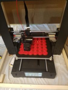
I did a pair of test prints and decided the 1 in. coins would be neat to hand out to everyone at the meet and greet, so at present, I’m printing up 36 of them at once. The raft is finishing up, but there are two spots where I think the coins will be lost. The first little bit of the raft just didn’t stick in that area. If those were solo prints, I’d abort them, but I’m not going to do so at the cost of the others.

I did what I could and cut away the bumps where the raft didn’t stick correctly. I had to work on the raft while the printer head was in motion (the left and right axis) because the pause feature parked the extruder head right above the damaged sections without a chance to get under them. Update: another layer on the raft brought the bumps back. With the bed moving this layer, I can only hope the defect doesn’t cost the other coins.

***

The printer finished after going all night and into the next afternoon. Three of the coins didn’t turn out well enough to give away. One didn’t even come off the raft at all. It turns out I was rushed in setting up the print. The close, left corner was aligned too low. That’s why the first layer of the raft didn’t stick. But in failure, I learned a little more about the structure of the raft. The outlines serve as a base for the first layer and so on and so forth until you get to the product.

As an extra little stunt, I’m making an extra, 3 in. coin along with a few smaller coins to replace the goofed ones and bring my total good coin count to about 40.

***

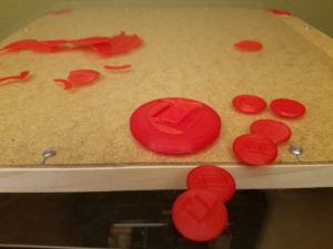
My stunt failed. I think the way I modeled it is to blame. The middle detail between the relief peeled. One of the eight smaller coins didn’t peel from the raft. In the end, I’m taking 42 coins to pass out.

***

I don’t have time to remodel. As a last ditch effort to make a bigger one for Tango, I’m printing up three 1.5 in. coins. *** Nope, they didn’t work. The printer switched to a short infill based layer to finish the dome. That’s why all my big ones and the very first prototype were goofs. Other than that, I would rather both T’s be of equal depth. Something must have gone accidentally right half way when modeling these.

***

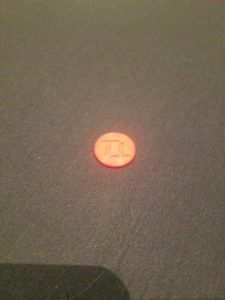
The Tango Tokens were a hit. Even though they weren’t perfect, they made for a cool, little souvenir for everyone. If I ever make more, I will want to remodel the coin and fuse all the pieces before they leave Blender. The printer was printing an internal membrane which led to the weak spot. On the other hand, maybe I can label future tokens with the event meetup. When I hold pretty much any 3D printed object to the light, I can see the infill lines. I want to try inserting a label in there to differentiate the production runs.

Final Question: have you ever made custom party favors, if so, what? And what for?

The Prototyping Process

Good Morning from my Robotics Lab! This is Shadow_8472, and today, I’m going over a short, but important side project I did this week. Let’s get started.

So, a few weeks ago, my mother made a request for a simple shirt clip. Using my skills I revived last week, I was able to get a satisfactory one in three prototypes. While learning the modeling software is an important step for me, I do not plan on providing a tutorial myself. When I go back and watch a tutorial, I will give the first lesson a link. What I do want to do is give tips on what I learn on my own.

The basic concept is a circle with a crossbar. I used a torus and a cylinder to model it in Blender. I didn’t have to go searching for the command to combine meshes, I just had to select both before exporting to a .stl file.

When it came time to print, the raft was a circle, probably because only the torus was digitally touching the print bed. My first and second prototypes were made from the same, tiny model; Cura saw Blender’s unitless distance in the .stl file as millimeters when I wanted inches. I learned to reliably scale models to a predictable size. When the second prototype came off the bed (the putty knife had a hard time with the uniform curve of the raft) there was this ridge that touched down to the bed. A few rough spots made it unsuitable for use on a shirt without first sanding it.

The third and current prototype had a model where the cylinder shared a radius with the height of the torus. This created a circle-slash raft, and it didn’t have so many problems with sharp artifacts from its manufacture. I wonder if the second prototype’s ridge on the bottom was an automatic support structure. I’ll need to print something that needs one to find out.

***

I have good news and bad news for myself. The good is that I figured out what the extra ridge on the second prototype was. The bad news is that it was a failed part of the print and not a support structure. I programmed up what looked like a lopsided sphere on a stick and told Cura to print it with and without a support structure. The only difference was that I got a raft with the shadow of the print instead of the contact point of it.

Final Question: I have heard about support structures sometimes being printed out of a different material. Are they ever printed like a raft you can peel off and sand down when needed?

From Blender to the Real World

Good Morning from my Robotics Lab! This is Shadow_8472, and today, I am learning to print a model from Blender. If all goes well, this should be a short post, but even if it isn’t, I should have my suspicions confirmed or refuted about the Z-axis progression. Let’s get started.

OK, so I did play around with Blender a few years ago. This time, I just want to make something simple as a proof of concept. A pyramid. I can set up my phone to take a picture every minute while I’m printing and then graph the progress with respect to time.

I won’t cover the setup and learning curve of Blender; there are a lot of tutorials out there. Just do not try to learn it by trial and error. You’re likely to get washed away with all the buttons and menus. My understanding is that it is NOT beginning user friendly, but at the same time, I understand it is basically the definitive free, open source 3D modeling software. Once you learn the core skills, you can move onto many other fields; like animation, still renders, game graphics, and (in this case) 3D printing.

I’ve had a desire to learn it for games, but I am still to develop my sills there.

***

The 3D printer is once again printing. The filament was a bit more painful to load than I remember. Good thing I didn’t unload it between each one. Anyway, I managed to use an old install of Blender to program up a pyramid to print. I actually took a cube and squished the top face down as far as it could go without actually making it an actual 5 pointed model. It’s close enough to what I need. I had to export it to a .stl file, not save, it.

This is my first print in the new case. Leveling the table was a little tight, but if it keeps the cat out, I can live with it. Anyway, there was a little bit of plastic messing with my leveling procedures. I need to get in the habit of cleaning the extruder tip while it is still warm. I suppose it shouldn’t matter too much. That’s what I think the raft is for, to get the print to a predictable place.

I chose to make a pyramid so I could graph the percent completion with respect to time. That was the hardest part of this week’s project. While I could have just sat there for two hours and recorded the percent every ten minutes, I went ahead and searched for an app to take a picture every one minute.

When I looked for such an app, I was assaulted by apps that offer to take time lapse videos of one sort or another, all these fancy fancy features and social connectivity… NO! I just want something to click the button every 60 sec. and make a separate file I can scroll through, and graph the results.

But I would say the hardest thing was setting up for the recording. I had to charge my phone, and rig a mount for it. Here’s the app I ended up using [Link], Timer Camera by Three Starfish.

My father actually did the bulk of the hardware arrangement. Nothing too fancy; the camcorder and tripod I used on the video posts usually lives at my church where we use it to stream our services on Saturday mornings. We didn’t bring it home this week, and I don’t intend to post these pictures anyway. Simple data collection.

***

I graphed the data. For every photo, I took  It’s almost linear, but there’s an inflection point where it speeds up rapidly after about 40 minutes. If this were simply a transition from raft and base layer to infill layers, that would explain things if it were z axis progression, but the second, faster part seems like it wants to be linear, but I’d need more data points for that. All I can do at this point is rule out percent time taken. I’d need a bigger/higher quality pyramid and a proper video of the progress bar.

Long story short: I took measurements of percent completion (almost) every minute. Now I want the min./sec. each percent is accomplished. It would be interesting to graph other shapes.

Final Question: I’ve eliminated time completed as the possible basis for percent completed. Maybe if I print up two more pyramids side by side (one after the other) that would give me more information. Anyway, What kind of shape would produce a graph that would look different if its completion was in plastic laid or z axis?