A New Tool Part 5

Good Morning from my Robotics Lab! This is Shadow_8472, and today, I bring part 5 of the construction of my Raspberry Pi prototyping platform with a camera. Let’s get started.

I am behind where I wanted to be. It’s the classic game of Hurry Up and Wait, only I waited too long. Things have to be done in order, and all the stuff where 2.5 hands were required feels like it was at the beginning.

It turns out whatever my intended way to measure the Pi Camera was overly complicated, as I was starting to figure. While I was looking to draw some kind of grid and view it at an angle and get help with the whole bunch of mathematical nonsense that produced, all I needed was the distance out and to either side as if following an upper case T. I didn’t even need to calculate the angle proper, because I could just add a cone with the proper dimensions.

The unforeseen challenge in stock for me this week was and in a way still is getting the model to comply. Long story short, Blender wants me to make quality meshes, otherwise it will crash. At least the stress test looks good for the auto recovery feature.

I made several prototype eyes for my camera to peek through. The first one based on the custom model of the Pi Cam had some gunk in there, but when my father was done introducing the razor to it, the piece fit perfectly and when I held it up to the camera, it could see through it perfectly. However, unlike the Blender model, the printed version had a hole where there was supposed to be a thin spot.

I printed up another version, this time on a higher quality and the circuit board bumped back a bit, so far, an extra bit on the camera didn’t need an extra hole I made for it. And that’s where I am now, modifying the hole model, with limited success. At the moment, I’m thinking I can drop some detail I no longer need, rather than keep at coaxing Blender into doing my will for it.

Final Question: Have you ever known exactly what needed to happen and not known what the controls were to make it happen?

A New Tool Part 2

Good Morning from my Robotics Lab! This is Shadow_8472, and today, I am continuing coverage of my new prototyping tool. Let’s get started.

I didn’t get as far as I thought I would this week. The mission this week was to get the top all printed, but that didn’t happen. The problem was that I didn’t already have all the skills to accomplish the task already, mainly proficiency in Blender. That’s my goal for next week, learn Blender well enough to finish modifying the upper half of the case.

As for what did get done, I managed to start developing the camera mount. The case I’m printing for my Raspberry Pi is based off a PacMan Ghost, printed in red. The first print, I used Blender to isolate the target eye from the rest of the 3D model, and printed it on fast. It took about 20 minutes, as opposed to a full day plus if I were doing the regular top on a respectable quality level. I drilled a hole in the printed piece and held it over the camera, using larger and larger drill bits until I didn’t see a red plastic border anymore.

For my second draft, I added a cylinder mesh in Blender and scaled one end down, forming a truncated cone. I used a Boolean filter on difference mode to cut out a hole for the lens. It didn’t fit well enough, so I printed another one with a more embellished cone.

My father taught me how to properly use a Vernier caliper. I already knew about the outside and inside edge measurement spots, but the the depth on the end of the ruler was new to me. Also new to me was the use of the Vernier scale; I never before got the idea that the extra marks on the slider were offset just a little bit. I think I had heard about the extra digit of precision, but only now did I get that only one was supposed to line up at once.

I used the caliper to measure up the camera. The plan from there is to model up a crude representation of it in Blender and use that to design the hole before I try printing up another pass. Giving some new thought to it, I want to angle the camera such that the ghost is looking at you, instead of “using peripheral vision.”

The next step may be boring, but it’s something I need to do. This week, I need to actually watch a few video tutorials on Blender. I already want to go through the videos by Blender Guru, Link to his channel. I’ve already tried going through his videos on the basics of Blender before, but I kept getting distracted. And no wonder! I just added the length of the videos I think I’ll need, the core Blender basics and the modeling basics, and it came out to almost six and a half hours! And most of that is in 45 minute chunks. The basic tutorial includes lighting and rendering tutorials, so in theory I could skip them for now, but I really should know how to use them.

Final Question: I’m at least somewhat likely to get more than one Pi computer in the foreseeable future. What kind of case should I search for to print up for the next one?

A new tool

Good Morning from my Robotics Lab! This is Shadow_8472, and today, I have shelved the boat race port pending review and started on a new project. Let’s get started.

My next goal is a project to keep the cat off the counter. After some early research, I came across OpenCV, an open source computer vision library. Some people have even already gotten it to identify cat faces. Keeping my long-term goal of a social robot in mind, this sounds like the direction to go, rather than a motion detector attached to a deterrent.

Now, to chose the hardware. I don’t know what the system requirements my program will need, so I decided to overshoot and make a “lab assistant” computer to help me with future small projects. A day or so of research later, taking into account Linux as a platform, system specs, community size, and likeliness of support form said community. Of note, I did try to include Fair Trade or equivalent as a criteria, but with electronics, it’s almost impossible to find a supplier who’s sure their product doesn’t include slave labor in their supply chain. In the end I narrowed it down to the Raspberry Pi 3 model B+. Also of note, the Pi is made in the UK (or China in peak times), so my guess is that at least some of the workers were more likely paid a fair living.

The assortment of starter packages is abundant. You can get the Pi alone for about $35, but starter packages tend to include other necessary things like a power cord and case. This led me to look into them and along the way, I learned that the Pi needs a micro SD card to run.

Before I even picked out the Pi for sure, I found a case to 3D print for it. In this case, it’s a Pac Man Ghost by Darren Furniss on MyMiniFactory.com. I started printing one up, but accidentally interrupted it about 10 out of 28 hours into printing the first part. No more heavy objects in front of a pressure based touch screen for me. While the second attempt was underway, the Pi itself arrived, and I set it up. A camera arrived with it, and I even managed to get a picture, though one test picture crashed the system. I haven’t gone to investigate yet.

The upper part of the case is the ghost’s head. Since I’m mounting a camera as part of the setup, I want to have the Pi look out one of its eyes (I’d need a second board to use a second camera). My first thought was to drill a hole but when I saw the narrow walls in the base with infill, I figured pulling the file into Blender and digitally drilling would be more effective. Before I do that, I need measurements so I drill the right hole and can actually mount the Pi camera correctly.

I started encountering small problems when I realized the Pi was mounted upside down in the ghost’s lower half, extending the distance the already short camera’s ribbon cable has to cover. After sundown Saturday, (I let my family have a day of peace from the printer’s constant whining during Sabbath hours) I started up a fast quality of the top. The file online said both parts were supposed to print without a support structure, but as I suspected, a short, long gap didn’t form correctly. I canceled the print, but learned a lot from the partial print.

Pulling the Pi from it’s kit case and putting it in the printed base, I discovered three things: The screw holes don’t quite line up (The case is meant for a Pi B and I have a Pi B+), and the gap in the top is necessary for port access for the power, if not the HDMI, and finally, by comparing the partial print to the 3d model, I discovered the eye does not line up at all with where the camera cable wraps around.

None of the challenges I’ve encountered so far are insurmountable. My only big concern is that the Pi will melt though the PLA case I have for it. Next week, I’m going to come up with a good 3d model for the ghost’s top where I can mount the camera.

Final Question: There is a real possibility I will need to switch to ABS for computer casings. What colors should I start with?

Massive Print Job

Good Morning from my Robotics Lab! This is Shadow_8472, and today, I am playing around with my 3D printer a little more. Let’s get started.

So, I’ve been watching Tango Tek, a Youtube personality [Link to his YouTube], off and on for a few years now. I’m currently a member of his Patreon MineCraft server and there’s a meet n greet for his patrons coming up (already past as of posting). I wanted to make a little something to give him, so I started with pocking about in Blender and turned Tango’s logo into a neat, little coin.

The 3D model is fairly simple. I took a short cylinder and carved the double T into a flattened sphere. I then overlapped the two, selected both pieces, and exported to .stl.

I found an acceptable use for the fast print. For my first coin I sized the print at 1 in. diameter. It didn’t look the greatest; but I figured that was because the printer doesn’t have the finest resolution on the layer thickness, and a 3 inch one I wanted to make would be fine.

Wrong.

The big one suffered from the same aesthetic problems. I ended up going back to Blender and reworking the cutout sphere. Stretching it into a more pronounced dome, I exported again.

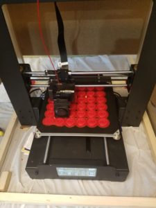
I did a pair of test prints and decided the 1 in. coins would be neat to hand out to everyone at the meet and greet, so at present, I’m printing up 36 of them at once. The raft is finishing up, but there are two spots where I think the coins will be lost. The first little bit of the raft just didn’t stick in that area. If those were solo prints, I’d abort them, but I’m not going to do so at the cost of the others.

I did what I could and cut away the bumps where the raft didn’t stick correctly. I had to work on the raft while the printer head was in motion (the left and right axis) because the pause feature parked the extruder head right above the damaged sections without a chance to get under them. Update: another layer on the raft brought the bumps back. With the bed moving this layer, I can only hope the defect doesn’t cost the other coins.

***

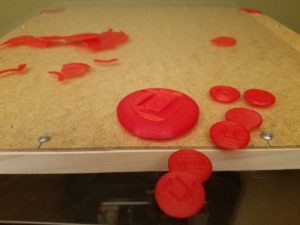
The printer finished after going all night and into the next afternoon. Three of the coins didn’t turn out well enough to give away. One didn’t even come off the raft at all. It turns out I was rushed in setting up the print. The close, left corner was aligned too low. That’s why the first layer of the raft didn’t stick. But in failure, I learned a little more about the structure of the raft. The outlines serve as a base for the first layer and so on and so forth until you get to the product.

As an extra little stunt, I’m making an extra, 3 in. coin along with a few smaller coins to replace the goofed ones and bring my total good coin count to about 40.

***

My stunt failed. I think the way I modeled it is to blame. The middle detail between the relief peeled. One of the eight smaller coins didn’t peel from the raft. In the end, I’m taking 42 coins to pass out.

***

I don’t have time to remodel. As a last ditch effort to make a bigger one for Tango, I’m printing up three 1.5 in. coins. *** Nope, they didn’t work. The printer switched to a short infill based layer to finish the dome. That’s why all my big ones and the very first prototype were goofs. Other than that, I would rather both T’s be of equal depth. Something must have gone accidentally right half way when modeling these.

***

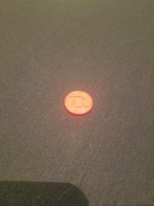
The Tango Tokens were a hit. Even though they weren’t perfect, they made for a cool, little souvenir for everyone. If I ever make more, I will want to remodel the coin and fuse all the pieces before they leave Blender. The printer was printing an internal membrane which led to the weak spot. On the other hand, maybe I can label future tokens with the event meetup. When I hold pretty much any 3D printed object to the light, I can see the infill lines. I want to try inserting a label in there to differentiate the production runs.

Final Question: have you ever made custom party favors, if so, what? And what for?

The Prototyping Process

Good Morning from my Robotics Lab! This is Shadow_8472, and today, I’m going over a short, but important side project I did this week. Let’s get started.

So, a few weeks ago, my mother made a request for a simple shirt clip. Using my skills I revived last week, I was able to get a satisfactory one in three prototypes. While learning the modeling software is an important step for me, I do not plan on providing a tutorial myself. When I go back and watch a tutorial, I will give the first lesson a link. What I do want to do is give tips on what I learn on my own.

The basic concept is a circle with a crossbar. I used a torus and a cylinder to model it in Blender. I didn’t have to go searching for the command to combine meshes, I just had to select both before exporting to a .stl file.

When it came time to print, the raft was a circle, probably because only the torus was digitally touching the print bed. My first and second prototypes were made from the same, tiny model; Cura saw Blender’s unitless distance in the .stl file as millimeters when I wanted inches. I learned to reliably scale models to a predictable size. When the second prototype came off the bed (the putty knife had a hard time with the uniform curve of the raft) there was this ridge that touched down to the bed. A few rough spots made it unsuitable for use on a shirt without first sanding it.

The third and current prototype had a model where the cylinder shared a radius with the height of the torus. This created a circle-slash raft, and it didn’t have so many problems with sharp artifacts from its manufacture. I wonder if the second prototype’s ridge on the bottom was an automatic support structure. I’ll need to print something that needs one to find out.

***

I have good news and bad news for myself. The good is that I figured out what the extra ridge on the second prototype was. The bad news is that it was a failed part of the print and not a support structure. I programmed up what looked like a lopsided sphere on a stick and told Cura to print it with and without a support structure. The only difference was that I got a raft with the shadow of the print instead of the contact point of it.

Final Question: I have heard about support structures sometimes being printed out of a different material. Are they ever printed like a raft you can peel off and sand down when needed?

From Blender to the Real World

Good Morning from my Robotics Lab! This is Shadow_8472, and today, I am learning to print a model from Blender. If all goes well, this should be a short post, but even if it isn’t, I should have my suspicions confirmed or refuted about the Z-axis progression. Let’s get started.

OK, so I did play around with Blender a few years ago. This time, I just want to make something simple as a proof of concept. A pyramid. I can set up my phone to take a picture every minute while I’m printing and then graph the progress with respect to time.

I won’t cover the setup and learning curve of Blender; there are a lot of tutorials out there. Just do not try to learn it by trial and error. You’re likely to get washed away with all the buttons and menus. My understanding is that it is NOT beginning user friendly, but at the same time, I understand it is basically the definitive free, open source 3D modeling software. Once you learn the core skills, you can move onto many other fields; like animation, still renders, game graphics, and (in this case) 3D printing.

I’ve had a desire to learn it for games, but I am still to develop my sills there.

***

The 3D printer is once again printing. The filament was a bit more painful to load than I remember. Good thing I didn’t unload it between each one. Anyway, I managed to use an old install of Blender to program up a pyramid to print. I actually took a cube and squished the top face down as far as it could go without actually making it an actual 5 pointed model. It’s close enough to what I need. I had to export it to a .stl file, not save, it.

This is my first print in the new case. Leveling the table was a little tight, but if it keeps the cat out, I can live with it. Anyway, there was a little bit of plastic messing with my leveling procedures. I need to get in the habit of cleaning the extruder tip while it is still warm. I suppose it shouldn’t matter too much. That’s what I think the raft is for, to get the print to a predictable place.

I chose to make a pyramid so I could graph the percent completion with respect to time. That was the hardest part of this week’s project. While I could have just sat there for two hours and recorded the percent every ten minutes, I went ahead and searched for an app to take a picture every one minute.

When I looked for such an app, I was assaulted by apps that offer to take time lapse videos of one sort or another, all these fancy fancy features and social connectivity… NO! I just want something to click the button every 60 sec. and make a separate file I can scroll through, and graph the results.

But I would say the hardest thing was setting up for the recording. I had to charge my phone, and rig a mount for it. Here’s the app I ended up using [Link], Timer Camera by Three Starfish.

My father actually did the bulk of the hardware arrangement. Nothing too fancy; the camcorder and tripod I used on the video posts usually lives at my church where we use it to stream our services on Saturday mornings. We didn’t bring it home this week, and I don’t intend to post these pictures anyway. Simple data collection.

***

I graphed the data. For every photo, I took  It’s almost linear, but there’s an inflection point where it speeds up rapidly after about 40 minutes. If this were simply a transition from raft and base layer to infill layers, that would explain things if it were z axis progression, but the second, faster part seems like it wants to be linear, but I’d need more data points for that. All I can do at this point is rule out percent time taken. I’d need a bigger/higher quality pyramid and a proper video of the progress bar.

Long story short: I took measurements of percent completion (almost) every minute. Now I want the min./sec. each percent is accomplished. It would be interesting to graph other shapes.

Final Question: I’ve eliminated time completed as the possible basis for percent completed. Maybe if I print up two more pyramids side by side (one after the other) that would give me more information. Anyway, What kind of shape would produce a graph that would look different if its completion was in plastic laid or z axis?


Ready for more

Good Morning from my Robotics Lab! This is Shadow_8472, and today, I am sidequesting into the world of drones for my first actual bot. Let’s get started!

I was seriously considering going for the PIXXY platform for what seemed like the longest time. Right now, I don’t know where I stand on what to build. I just want to find something I know I won’t run out of non-printable parts for. PIXXY appears to be a dead platform at second glance as many of the parts listed for it 404 on me. I’m willing to look into alternative parts for the same platform, though.

***

The first penetration attempt into the field was a big let down. Preassembled drones can run cheaper than the electronic goodies needed to build an open source design, and I am not ready to design my own chassis based off a stripped down model, or even a kit. The experience felt a little… bitter, even if it was only over the phone.

On the other hand, getting a preassembled drone would give me a quicker feel for how a drone is supposed to fly.

Another thing to consider: replacing a drone from a factory will cost more if it breaks than printing up a single replacement part. Besides, one of the rules I laid out for myself is to only use free, open source stuff whenever possible.

***

OK, OK, I gave it some more thought, a prearranged kit (not preassembled) wouldn’t be so bad if all the parts are standardized anyway. I would still want to make sure the parts are ones that will fit with whatever drone I decide to print.

***

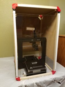
I didn’t seem to come to any substantial conclusions this week, but my father and I did finish the temporary case once and for all. The breathing holes on the sides have window screening stapled to them and we got some cheap J channel to hold the door, which is now a slide up model. Screws hold the rails for the door in place, and a little black duct tape protects the clear panel from further scratches as it slides.

Final Question: If I don’t go with building the Pixxy, what printable model should I go for?

Construction of the 3D Printer Case Part II

This week’s edition is available on my YouTube channel.

Good Morning from my Robotics Lab! This is Shadow_8472, and today, I am printing up the remaining corner brackets for my 3D printer case. Let’s get started.

This week, I decided to explore the different quality settings for my printer’s slicer program, Cura. As I start writing this week’s post, I’m printing out the third of eight corner brackets, each one so far sliced at different quality level. The only obvious difference is the time required to print. As I posted last week, I suspect the raft comes off more easily the higher the print quality, but I’m waiting on drawing final conclusions for now, since the easy raft removals were from .gcode patterns that shipped with the printer and I have no way of knowing what level of quality they were sliced with.

I’m also noticing this webbing stuff across crevices in all three bracket qualities. Judging by the print in progress, I’m guessing the infill is spaced progressively tighter on the higher quality prints, but the official call will wait until I have my final sample. Of note: the printer sounds fairly consistent no matter the printing quality.

***

Progress bars are wonderful estimation tools. The Printer has one. But I don’t think it measures progress in terms of either time or plastic used so far. There are times when it feels like the job is lagging behind schedule as it chugs through big layers only for the progress bar to catch up as it blitzes through smaller, faster layers. I believe the printer is simply measuring percent completion in terms of Z axis progress. Another easily programmable possibility would be to report percentage of the .gcode file executed. But exploring that question should be a topic for another week where I also cover learning the basics of Blender.

With that said, the third bracket just came off the printer. Toward the end, the printer screen dropped the print job monitor in favor of the main menu. What’s going on with that? End of .gcode file? I’ll need to keep that quirk under observation in the future.

***

The webbing seems to be about the same density and strand size no matter what quality I print on. The brackets each weigh in at .7 oz; if they differ at all, I don’t have a precise enough scale to tell. The rafts from high and normal quality jobs came off cleanly within seconds by hand, but the low quality raft split on removal, requiring additional cleanup later. The webs will also require some tools to extract, but the toughest thing about them is the tricky angle for fingers. The infill on the high and normal settings is the same, but the fast print is only 2/5 as frequent. Interestingly, the sides of the normal bracket and not the low quality one, are the roughest. Ironically the top tips of the corners of the “high” quality print didn’t stick correctly and broke off. In conclusion: I’m going to use the normal setting for the remaining brackets.

***

I messed around in Cura some more and I started printing the next two brackets at once. I wonder what the overall quality difference will be. The extruder tip is alternating brackets, laying a layer down on one then the other. It takes a little longer, but combining jobs saves time on resetting the printer. I can only guess that there will be a bunch of webbing connecting these print bed twins.

All the rafts for these brackets so far are triangular, but on all the normal prints, and only on the normal prints, one or two corners of the raft get omitted, including each of the twins. Messing with Cura again, I found the size controls to make objects bigger or smaller. Those get left alone for now.

***

The twin brackets are almost done. They do indeed have a bit of webbing between them, but it isn’t so bad. I’m not sure, but there might be less self webbing per bracket than any of the singles. I’ll need to run many more print cycles to know for sure.

***

Filming for this week’s presentation was riddled with challenges. I tried filming the twins, but I quickly ran out of storage on the camera. Bracket number six was printed on low quality so the camera could swallow filming it  from start to finish. Unfortunately, the sun went down and the lights inside were off, so that take was botched due to low light at the end. The raft didn’t peel nicely either, instead it royally fractured along where bracket met raft. I ended up bumping the quality on the camera down a level to capture the single, normal-quality bracket number seven being printed. After this one is done, I’ll have one more to print up before next week’s topic where I finish the printer case.

***

Final Question: Do you know a lot about 3D printing? What’s going on with all these plastic fibers?

Construction of the 3D Printer Case Part I

Good Morning from my Robotics Lab! This is Shadow_8472, and today, I am printing out the corner brackets of the anti-cat case for my 3D printer. Let’s get started.

The best projects are those that build upto higher existing goals. This week is printing files from online. The Cura software my 3D printer came with is apparently what is known as a slicer. From my research, you can model up any 3d object with as much precision as the limitations of your computer will let you. But in the end, the 3D printer can only print so small. A slicer translates a 3D object file of pure mathematics into a set of instructions for the printer to follow. For the purposes of this blog, Cura is a software extension of my printer.

There are two ways to get the sliced pattern to the printer. SD card, or USB cable. I don’t have enough USB extensions to reach the printer, so I’m operating on SD card right now. I only have one USB card reader on a modern machine, but I remembered one of our old computers in the garage having a multi-card reader. I extracted the module, but quickly learned there weren’t any appropriate internal connectors. The old computer in question was using PATA cables, which look like ribbons instead of the more wire shaped SATA cables of more recent years. Maybe in the future, I’ll see if soldering something up is an option.

I used the rest of my sample filament to print up a potential bracket to hold my 3D printer case. I knew I’d run out before the printer finished, but the sample produced was enough to know a finished version, even one scaled up to be big enough wouldn’t work. Of note, I told Cura to do a fast job on the piece, and I had a harder time separating the raft from the bracket. I’m going to do some more experimentation when I print up the upper corners. The regular print speed is estimated at 6+ hours and the fast at about 3+. Expect the full results next week.

The part I am printing for this project can be found here. The linked page provides the download and says it’s in what’s known as Creative Commons. While I don’t know exactly what that means, I understand it to mean the file creator gives permission to anyone to use their part for whatever purpose without royalties, even if it is part of your product you sell.

***

I have started the first corner, on fast, and it should take between 3 and 3.5 hours. I opened up my first full spool of filament. Setting up this job took longer than expected. First of all, the 1KG spool didn’t fit on the spool rack, so my father and I had to improvise a wide enough one. A more permanent fix may involve printing up a part to fit correctly.

I also had trouble loading the new filament. The instructions said to cut an inch off at an angle, and I did, but it kept having trouble grabbing it. The last, little bit  of the white sample filament was still in there, so I set it up and told it to go. The thing started printing a ghost raft.

The filament wasn’t loaded properly. I tried preheating and loading a few times, but I told it to load, it kept making a clicking noise like it couldn’t grab the end. I had to cut it again at a steeper angle before the machine took it. The extruder oozed a white string that turned red as it went. I was secretly hoping to have the color change happen on the raft for the bracket, but seeing it working correctly was also good. In pulling the tangle away, the hot plastic formed a fine thread, as fine as human hair, though it didn’t feel as strong.

***

Half done, and no major problems remaining so far. I am noticing a bunch of places where the filament is forming like a web in places where it isn’t required. My guess is that’s the fast mode complaining a little. I’ll have to clean the visible ones out. I’m also not getting the Forbidden Planet feeling like before. Either I’m getting used to the sound of the printer or it’s the fast mode. Maybe I’ll print up one on each setting and compare them side by side. Weight, Raft separation, and print time should come into play. I should also take note which corner is which in the case one of them cracks while the case is being assembled or later during use.

Of note, some of my first builds seemed to have some stuff printed into them. I wonder if some stuff from my hands got onto the sample filament and the printer passed it.

***

The print job finished. I’m going to leave the raft on until I have the “normal” and “high” quality prints of the same job done. Final Question: I had to ward my cat off of my printer part way through. Have you ever had a pet almost hurt themselves on a hobby project?

A Summery of Goals

Good Morning from my Robotics Lab! This is Shadow_8472, and today, I am not doing anything too exciting. Just a quick touch up on last week’s topic and then I have some thoughts on building milestones for myself to reach. Let’s get started.

I ended up using the rest of the sample filament on a pair of unknown prints from the sample SD card. One turned out to be a sitting elephant and another was a scaled up version of the butterfly that came attached to the printbed when the printer shipped. Of note, the first layer of the raft was of a different thickness each time. Of course, I rechecked the printbed each print, and I got a little better pseudo-understanding of how the printer in at work is supposed to sound. I’d like to upload a video with a sample, but this week was a little too slow for my intended project.

Future plans. I still want to build and program a social robot, but I definitely need some intermediate steps before I get there. I wasn’t planning on the 3D printer at this point, but since I have it, I’d like to use it. My sister suggested I build a drone, and after rejecting the idea, rethinking it, and deciding it wasn’t a bad idea after all, I decided to research the best one for my purposes.

There is A LOT of information out there about 3D printing drones. Lots of it is up and above my level for now, and since drones aren’t my goal, I’m looking for a lower-cost drone I can print myself. It turns out a lot of the results for 3D printed drones are about getting drones that happen to have been 3D printed. So far, the only drone I have seriously considered is the Pixxy drone. It’s fairly small and cheap to build. Just what I need to learn some stuff from it and move on.

After I am done learning with the drone, I really need to check into learning about ROS. At that point, I should look into learning Gazebo alongside it. Learning some more about Linux, like remoting in to another machine should come in handy for when I build a more advanced bot running Linux with ROS on top.

But everything else aside, I have animals in the house. The 3D printer is a new thing. The dogs went to check it out and seem willing to leave a print job in place for now. My cat Orbit, though, can’t seem to go a day without gettin’ into trouble of one sort or another. The printer needs a case to keep him out. I’m hoping that will be next week’s project.

Final Question: Do you have any experience in 3D printing drones? If so, know any good, entry level ones?