
Good Morning from my Robotics Lab! This is Shadow_8472 and today, I am assembling and testing my first prototype artificial muscle. Note that this is not a tutorial, but a work in progress; I’ll be making more elaborate updates when I finish each phase of prototyping. Let’s get started!
Initial Construction
In case you missed my last post on McKibben artificial muscles, I’m using some surgical tubing with a in a braided ASA plastic sleeve as the main body of my muscle. Starting out, I’m using a bicycle pump for my air supply and some old, mostly cotton string for holding the ends together. We cannibalized some old garden drip line for structure in the inflation end, and a screw on the other end.
Assembly started with cutting around 12 inches each of tubing and sleeve. The sleeve unravels like crazy when being stretched, so I melted one end with a candle lighter. The mouth was nice and tight, but it was stuck contracted. I fed tubing in the other end melted that end open. I inserted the two inch length of drip line and screw into their respective ends and tied them off.
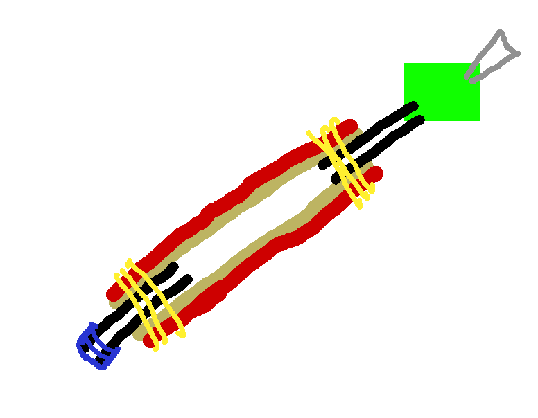
I drew this picture in GIMP for my father’s benefit before construction, but it highlights a “green part” between the actual muscle and the bicycle pump (gray triangle). Note this was drawn before I added the screw on the solid end and the blue parts are painter’s tape that lasted about as long as it took to try taping the muscle to a ball inflation tip for the pump.
First Actuations
There was no way my chosen string was holding at pressures required to inflate the muscle, so we moved to zip ties. We also redesigned the adapter to use rubber tubing wrapped in duct tape to resist inflation. It happened anyway when the rubber expanded lengthwise as well as radially. After extending the tape just a little farther, I started pumping as the hiss of gas escaping the system made it difficult to focus on the pump’s pressure gauge.
We ran a number of tests, and over about 10 inches of workable muscle, the whole thing contracted to about 8.5 inches and expanded from 3/8 inch to 1/2 inch diameter – about as thick as the casing would go according to tests later on.
Development continued after the pictured state. We had some irreconcilable leaks with the zip ties and switched to more expensive pipe clamps while we dreamed of ordering some rubber tubing with a thinner wall. The Green Part was replaced again with more plastic tubing probably intended for water, and accordingly leaky at its adapter. Only the very tip is still rubber tubing, and that’s only to create a seal someone has to hold closed while the system is under pressure.
Speaking of pressure, every improvement raised the maximum possible pressure before something failed or was otherwise too loud to tolerate. We made several milestones, but eventually maxed out the pump at 150 PSI, though after I sealed the leaky connector with some proper sealant tape, air stopped escaping until 80 PSI, but when it started, it was painfully high in pitch.
Takeaway
My finger pads HURT after assembling that thing. It could be working with the braided plastic or messing with the pipe clamps, but I don’t see many of my materials being final picks. The contraction ratio is lacking, the tube is high pressure, and if I’m going to be using a lower pressure anyway, I might as well go back to zip ties.
Final Question
During testing, I kept going to higher pressures because I was operating under the hypothesis that there was more contraction to be had. The calipers said otherwise; manually squishing the casing off the spool it came on gave about the same diameter. I identified my false impression as coming from the fact that the woven casing came flattened out, and my mind wasn’t translating diameter and half circumference properly. What hypotheses have you discarded while working with something?